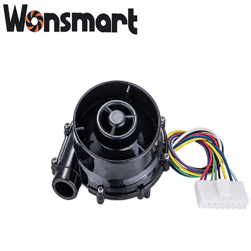
DC24V Small Inflatable Blower Mini Centrifugal Blower Fan 7kpa Pressure

Blower features:
| 1.Product Introduction |
| Part No |
WS7040-12-X200N |
| Vlotage |
12VDC |
| At Max airflow |
| Speed |
35,000rpm |
| Current |
4.5A |
| Air flow |
25m3/h(14CFM) |
| Noise |
73dba |
| At Max air pressure |
| Speed |
43,000rpm |
| Current |
1.5A |
| Air Pressure |
6Kpa |
| Noise |
70dba |
| Block |
50dba |
Product details:
Blower Performance:
WS7040-24-V200 blower can reach maximum 22m3/h airflow at 0 kpa pressure and maximum 6.8kpa static pressure. It has maximum output air power when this blower run at 3kPa resistance if we set 100% PWM. It has maximum efficiency when this blower run at 5.5kPa resistance if we set 100% PWM. Other load point performance refer to below P-Q curve:
Application
The WS7040-24-V200 is a compact and powerful centrifugal blower that delivers efficient airflow for a variety of applications, including small inflatable blowers. With a voltage rating of 24VDC and a maximum airflow of 25.5m3/h (14CFM), this blower is an ideal choice for creating a steady flow of air to inflate small inflatables.
At its maximum speed of 37,000rpm, the WS7040-24-V200 draws a current of 2.7A, providing a continuous flow of air that allows small inflatables to be inflated quickly and easily. Despite its powerful performance, this blower produces a noise level of only 73dba, making it a relatively quiet option for inflating small inflatables.
In summary, the WS7040-24-V200 is a highly versatile and efficient centrifugal blower that is perfect for use in small inflatable blowers. Its powerful airflow, low noise level, and compact size make it an excellent choice for inflating small inflatables in a variety of settings. If you are looking for a reliable and efficient blower for your small inflatables, the WS7040-24-V200 is definitely worth considering.
Customized process:
The centrifugal fan uses the centrifugal power supplied from the rotation of impellers to increase the kinetic energy of air/gases. When the impellers rotate, the gas particles near the impellers are thrown off from the impellers, then move into the fan casing. As a result, the kinetic energy of gas is measured as pressure because of the system resistance offered by the casing and duct. The gas is then guided to the exit via outlet ducts. After the gas is thrown-off, the gas pressure in the middle region of the impellers decreases. The gas from the impeller eye rushes into normalize this. This cycle repeats and therefore the gas can be continuously transferred.

 Your message must be between 20-3,000 characters!